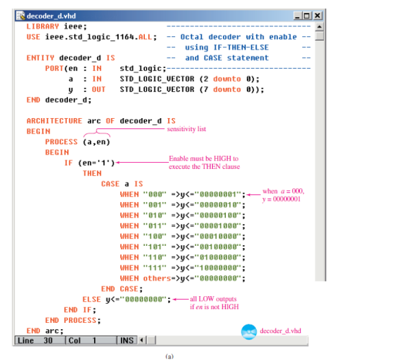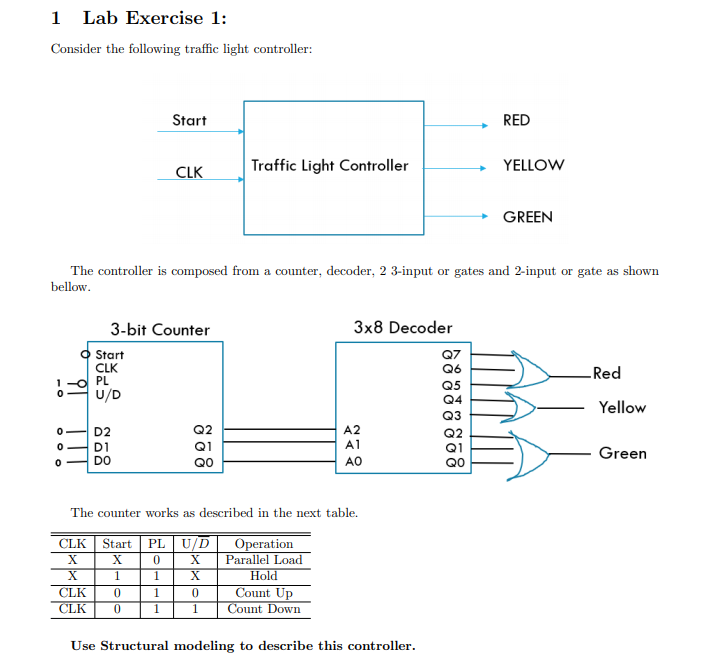
The following is the VHDL code for 3x8 decoder in behavioral style along with the test bench.
Now that we have written the VHDL code for an encoder, we will take up the task of writing the VHDL code for a decoder using the dataflow architecture.As customary in our VHDL course, first, we will take a look at the logic circuit of the decoder.
- Design 3:8 decoder in VHDL Using Xilinx ISE Simulator Searches related to Design 3:8 decoder in VHDL vhdl code for 3 to 8 decoder using behavioral modelling vhdl code for 3 to 8 decoder using 2 to.
- USEFUL LINKS to VHDL CODES. Refer following as well as links mentioned on left side panel for useful VHDL codes. D Flipflop T Flipflop Read Write RAM 4X1 MUX 4 bit binary counter Radix4 Butterfly 16QAM Modulation 2bit Parallel to serial. RF and Wireless tutorials.
library IEEE;
entity deco1 is
y : in STD_LOGIC;
d0 : out STD_LOGIC;
d2 : out STD_LOGIC;
d4 : out STD_LOGIC;
d6 : out STD_LOGIC;
end deco1;
component decand1 is
b : in STD_LOGIC;
d : out STD_LOGIC);
component decnot1 is
c : out STD_LOGIC);

signal s2, s1, s3: STD_LOGIC;
g1: decnot1 port map(x,s1);
g3: decnot1 port map(z,s3);
g5: decand1 port map(s1, s2, z, d1);
g7: decand1 port map(s1, y, z, d3);
g9: decand1 port map(x, s2, z, d5);
g11: decand1 port map(x, y, z, d7);
- TEST BENCH
LIBRARY ieee;
ENTITY deco2_tb IS
-- Component Declaration for the Unit Under Test (UUT)
COMPONENT deco1
x : IN std_logic;
z : IN std_logic;
d1 : OUT std_logic;
d3 : OUT std_logic;
d5 : OUT std_logic;

d7 : OUT std_logic
END COMPONENT;
--Inputs
signal y : std_logic := '0';
--Outputs
signal d1 : std_logic;
signal d3 : std_logic;
signal d5 : std_logic;
signal d7 : std_logic;
BEGIN
uut: deco1 PORT MAP (
y => y,
d0 => d0,
d2 => d2,
d4 => d4,
d6 => d6,
);
stim_proc: process
x<='0'; y<='0';z<='0';
3x8 Decoder Truth Table
x<='0'; y<='0';z<='1';


x<='0'; y<='1';z<='0';
3 To 8 Decoder Vhdl
x<='0'; y<='1';z<='1'; wait for 100ns;
x<='1'; y<='0';z<='1';wait for 100ns;
x<='1'; y<='1';z<='1';wait for 100ns;

END;
Test Bench Waveform:
